MIPI CSI2 Brdge芯片,转成LVDS信号,便于FPGA接收。MC20901 5 Channel FPGA Bridge IC for MIPI D-PHY Systems and SLVS to LVDS Conversion。
1 General Description
The MC20901 is a high performance 5 Channel FPGA bridge IC, which converts MIPI D-PHY compliant input streams into LVDS high speed and CMOS low speed output data streams.
The MC20901 can also convert an SLVS signal into an LVDS signal. The MC20901 outputs can be directly connected to FPGAs or DSPs.
Data rates range from 0 Mbps to 2.5 Gbps in HS (High Speed) mode and up to 20 Mbps in LPDT (Low Power Data Transmission) mode.
2 Key Features
Input is compliant to MIPI D-PHY interfaces using the DSI, CSI-1 and CSI-2 standards
o HS mode data rate: up to 2.5 Gbps
o LPDT mode data rate: up to 20 Mbps
Conversion of SLVS input to LVDS output
o SLVS data rate: up to 2.5 Gbps
BTA (Bus Turnaround option for Channel A or E)
Pin swap option (all channels simultaneously)
5 Channel device (e.g. 4x DATA, 1x CLK)
D-PHY input termination automatically switched depending on HS or LP mode
No additional level shifters needed
Arbitrary power up sequence
Available as a bare die
o RoHS compliant, Pb-free
Available in a TQLMP-48 package
o 7mm * 7mm * 0.9mm
o 0.5mm pitch
o RoHS compliant, Pb-free

Table of Contents
1 General Description .......................................................................................................................... 4
2 Key Features ..................................................................................................................................... 4
3 Block Diagram ................................................................................................................................... 5
3.1 Block Diagram ........................................................................................................................... 5
4 Parametrics ....................................................................................................................................... 6
4.1 Absolute Maximum Ratings....................................................................................................... 6
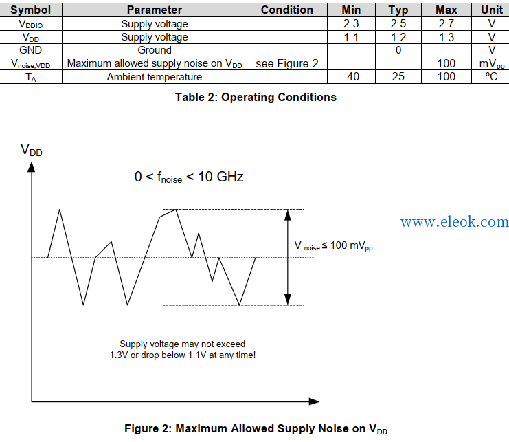
4.2 Recommended Operating Conditions ....................................................................................... 6
4.3 DC Characteristics..................................................................................................................... 7
4.4 AC Characteristics ..................................................................................................................... 8
5 Package Information ......................................................................................................................... 9
5.1 TQLMP-48 Package .................................................................................................................. 9
5.2 Pin Description........................................................................................................................... 9
5.3 Package Information................................................................................................................ 11
6 Application Notes ............................................................................................................................ 12
6.1 Application Overview ............................................................................................................... 12
6.2 D-PHY to FPGA Bridge Application......................................................................................... 13
6.3 D-PHY to FPGA Bridge Application with Bus Turnaround ...................................................... 14
6.4 Signal Levels ........................................................................................................................... 15
6.4.1 HS-X-P and HS-X-N LVDS Outputs *) ............................................................................. 15
6.4.2 LP-X-P and LP-X-N CMOS Outputs *)............................................................................. 15
6.4.3 DPHY-X-P and DPHY-X-N Inputs *) ................................................................................ 15
6.4.4 GPIO-0, GPIO-1, BTA, PINSWAP CMOS Inputs............................................................. 15
6.5 Configuration Using GPIO-0 and GPIO-1................................................................................ 15
6.6 Configuration Using BTA ......................................................................................................... 15
6.7 Configuration Using PINSWAP ............................................................................................... 15
6.8 Input to Output Signal Diagram ............................................................................................... 16
7 Legal Disclaimer Notice .................................................................................................................. 17
8 Contact Information......................................................................................................................... 17
文档下载:
 MC20901-V1_08.pdf
(920.6 KB, 售价: 5 E币)
【必读】版权免责声明
1、本主题所有言论和内容纯属会员个人意见,与本论坛立场无关。2、本站对所发内容真实性、客观性、可用性不做任何保证也不负任何责任,网友之间仅出于学习目的进行交流。3、对提供的数字内容不拥有任何权利,其版权归原著者拥有。请勿将该数字内容进行商业交易、转载等行为,该内容只为学习所提供,使用后发生的一切问题与本站无关。 4、本网站不保证本站提供的下载资源的准确性、安全性和完整性;同时本网站也不承担用户因使用这些下载资源对自己和他人造成任何形式的损失或伤害。 5、本网站所有软件和资料均为网友推荐收集整理而来,仅供学习用途使用,请务必下载后两小时内删除,禁止商用。6、如有侵犯你版权的,请及时联系我们(电子邮箱1370723259@qq.com)指出,本站将立即改正。
|