完整文档下载
 dianzifa001.pdf
(2.03 MB, 售价: 1 E币)
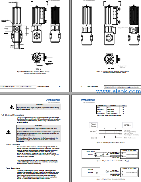
This manual provides installation, maintenance, and operating instructions for the HFG2.0Gas Fuel Metering Valve.Every attempt has been made to provide sufficient information in this manual for theproper operation and preventive maintenance of the valve. Read this manual in itsentirety to fully understand the system.Operating the HFG2.0 Gas Fuel Metering Valve in accordance with instructions hereinensures long term and reliable operation.
目录
Purpose of This Guide..............................................................................................................................iii
Product Identification................................................................................................................................iii
What the User Should Know....................................................................................................................iv
Related Publications.................................................................................................................................iv
1 INSTALLING THE HFG2.0......................................................................................................................1
1.1 Before Beginning...............................................................................................................................1
1.2 General Specification Summary........................................................................................................3
1.3 Mechanical Installation ......................................................................................................................4
1.4 Electrical Connections .......................................................................................................................15
2 UNDERSTANDING THE HFG2.0 ...........................................................................................................26
2.1 System Description............................................................................................................................26
2.2 Electrical Description .........................................................................................................................27
2.3 Mechanical Description......................................................................................................................31
2.4 Identification Plate..............................................................................................................................37
3 OPERATING THE HFG2.0......................................................................................................................40
3.1 Powering Up......................................................................................................................................40
3.2 Finding Home Position.......................................................................................................................40
3.3 Holding Motor Current State..............................................................................................................41
3.4 Moving to Stop Position.....................................................................................................................43
3.5 Controlling Motion..............................................................................................................................43
3.6 Resetting the Actuator.......................................................................................................................45
3.7 Monitoring System Health..................................................................................................................46
3.8 Changing Set-Up Parameters ...........................................................................................................51
4 MAINTAINING THE HFG2.0 ...................................................................................................................54
4.1 Refurbishment ...................................................................................................................................54
5 TROUBLESHOOTING.............................................................................................................................56
5.1 FAULT File ........................................................................................................................................60
APPENDIX A: DECOMMISSIONING & DISPOSAL.....................................................................................62
APPENDIX B: GLOSSARY...........................................................................................................................64
Figure 1-1. Typical HFG2.0 Gas Fuel System Installation...............................................5
Figure 1-2. Alternate HFG2.0 Gas Fuel System Installation ............................................5
Figure 1-3. HFG2.0 Dimensions, 3-Piece Housing..........................................................9
Figure 1-4. HFG2.0 Dimensions, 1-Piece Housing........................................................10
Figure 1-5. HFG2.0 Mounting Orientations....................................................................11
Figure 1-6. HFG2.0 Mounting Provisions, 3-Piece Housing (Standard Mounting).........12
Figure 1-7. HFG2.0 Mounting Provisions, 1-Piece Housing (Standard Mounting).........13
Figure 1-8. HFG2.0 Mounting Provisions, 1-Piece Housing (Reversed Mounting)........14
Figure 1-9: HFG2.0 System Power Wiring Diagram......................................................16
Figure 1-10. Typical Power Connection With Power Supply..........................................16
Figure 1-11. Typical Power Connection With Battery ....................................................16
Figure 1-12: HFG2.0 System Signal Wiring Diagram ...................................................20
Figure 1-13. Typical Analog Input Connection...............................................................21
Figure 1-14. Typical Analog Output Connection............................................................21
Figure 1-15. Typical Discrete Input Command Connection ...........................................21
Figure 1-16. Typical Discrete Output Alarm Connections..............................................22
Figure 1-17. Typical RS232 Serial Interface Connection...............................................22
Figure 2-1. HFG2.0 Electronics System Block Diagram................................................29
Figure 2-2. HFG2.0 Cut-Away View – Actuator Main Housing Assembly......................35
Figure 2-3. HFG2.0 Cut-Away View (Partial).................................................................36
Figure 2-4. Typical Identification Plate ...........................................................................37
Figure 2-5. Typical Refurbishment Plate........................................................................38
Figure 3-1. HFG2.0 Basic Operation Flow Chart...........................................................42
Figure 3-2. HFG2.0 Actuator Position vs. DEMAND......................................................44
Figure 3-3. Dead Band of Actuator, Position vs. DEMAND Curve.................................45
Table 1-1. Wire List for HFG2.0 Power Harness............................................................16
Table 1-2. Power Supply Requirements........................................................................17
Table 1-3. Wire Size for HFG2.0 Power Harness..........................................................18
Table 1-4. Wire List for HFG2.0 System Signal Harness...............................................19
Table 1-5. Computer COM Port Pin Outs......................................................................23
Table 1-6. Wire Size for HFG2.0 Signal Harness ..........................................................24
Table 3-1. Default Configuration For FAULT Alarm ...............................................48
Table 3-2. Default Configuration For OVERTEMP Alarm ......................................48
Table 3-3. Fault Configuration For FAULT Alarm ........................................49
Table 3-4. Fault Configuration For OVERTEMP Alarm ...............................50
Table 3-5. Typical HFG2.0 Setup Parameters With Default Values ..............................52
Table 5-1. Initial Installation Troubleshooting Chart .......................................................58
Table 5-2. HFG2.0 In-Service Troubleshooting Chart....................................................58
Table 5-3. HFG2.0 Electrical Continuity Troubleshooting Chart ....................................59
部分内容截图

【必读】版权免责声明
1、本主题所有言论和内容纯属会员个人意见,与本论坛立场无关。2、本站对所发内容真实性、客观性、可用性不做任何保证也不负任何责任,网友之间仅出于学习目的进行交流。3、对提供的数字内容不拥有任何权利,其版权归原著者拥有。请勿将该数字内容进行商业交易、转载等行为,该内容只为学习所提供,使用后发生的一切问题与本站无关。 4、本网站不保证本站提供的下载资源的准确性、安全性和完整性;同时本网站也不承担用户因使用这些下载资源对自己和他人造成任何形式的损失或伤害。 5、本网站所有软件和资料均为网友推荐收集整理而来,仅供学习用途使用,请务必下载后两小时内删除,禁止商用。6、如有侵犯你版权的,请及时联系我们(电子邮箱1370723259@qq.com)指出,本站将立即改正。
|